Pedal Mods · Ibanez
Ibanez TS-9 & TS-808 Mod Kit
The kit for this installIbanez TS-808 Tube Screamer Modifications
Don't have the kit yet? Order the Ibanez TS-808 Tube Screamer Modifications
Parts
- 47pf cap 47 pF ceramic (MLCC) pack
- .047uf cap - 473 47 nF ceramic (MLCC) pack
- .22uf cap - 224 × 2 220 nF ceramic (MLCC) pack
- 1uf cap - 105 × 2 1 uF ceramic (MLCC) pack
- 10uf cap - 106
- 47uf 25Vmin
- 100uf 25Vmin Nichicon KZ 100 uF 25 V (4-pack)
- 100 ohm resistor 100 Ω 1/2 W 1% metal film, 100 pcs
- 3.3k resistor 3.3K 1/2 W 1% metal film, 100 pcs
- 10k resistor 10K 1/2 W 1% metal film, 100 pcs
- LED Opaque × 2
- LED Clear
- Low Noise Opamp
Don't have the kit? Order the Ibanez TS-808 Tube Screamer Modifications
A 1/2 W 1% metal film resistor kit covers every 1/2 W value in this list: MOKMMKIT 150-value kit
Tools
- Soldering Iron Hakko FX-888DX
- Solder Kester 44 62/36/2 silver-bearing, 0.025", 1 lb (the shop's) · Kester 44 60/40, 0.025", 3/4 oz
- De-Soldering Braid Soder-Wick #2 (narrow, for pedals)
- Phillips Screwdriver Klein 85808 screwdriver set
- Wire Clippers Hakko CHP-170 (2-pack)
Some links here are affiliate links. As an Amazon Associate I earn from qualifying purchases.
1
Getting started
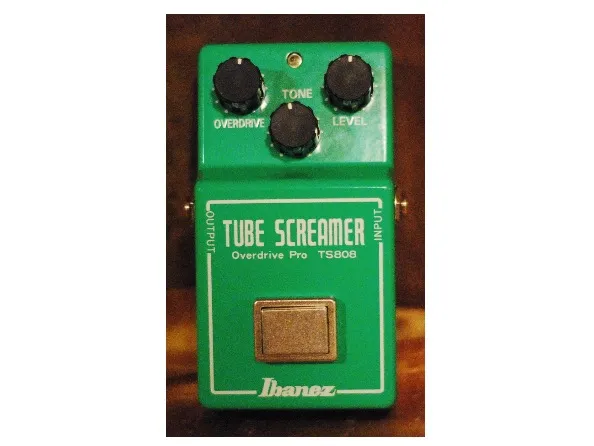
- CAUTION: Read all these instructions before beginning, if your pedal is currently under warranty it will not be after these mods. This kit and the instructions do not include any warranty of any kind and you agree to hold harmless the seller of this kit against any and all claims.
- Thank you for purchasing the Ibanez Tube Screamer Supreme Mod Kit. After these mods you will not believe it’s even the same Pedal. Included are all the components necessary for total tone transformation, it replaces key components in the signal path to turn your Tube Screamer into a serious tone machine.
- There is also a new LED to replace the red one, it will not change the tone of the pedal, just change the color of the light.
- Open up the back and take a look inside. There is the main circuit board held by a single screw and a tiny board that only houses the LED. There is no need to remove the jacks or pots for this Kit.
2
Replacing components
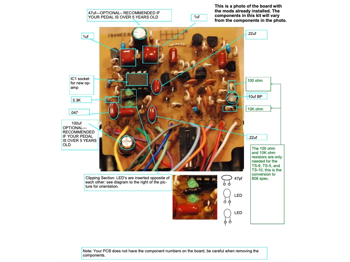
- After the board is exposed it’s time to start removing components and replacing them with the new ones. Make sure the battery is removed and no cables or AC- adaptors are plugged in.
- NEVER heat the solder and try to pull the component out you WILL damage the PCB. Use solder wick to completely remove the solder and the component will come free easily.
- The LED’s, chip, 100uf and 47uf caps, must be inserted correctly in order to work.
- On the LED the longer lead goes toward the red wire. The chips and sockets have a notch that should line up with the notch shown on the board. Insert the sockets and chips the same way it’s shown on the example on the next two pages. For the 100uf and 47uf caps the shorter lead goes toward the black band.
3
18V operation
- For 18V operation you must install the 100uf and 47uf cap from the pic in the last photo
4
Finish!
- After swapping out the parts put your pedal back together and enjoy your new pedal!
- Troubleshooting: Check to make sure that the soldering all looks shiny and that two pads aren't bridged by too much solder. Check to make sure no pads have lifted, if they have you can use a lead cut off a component to connect the broken connections. Check to make sure that none of the wires have come loose at the top of the PCB and fix them if so